Using the fragment position in a fragment shader is quite useful, but it is far from
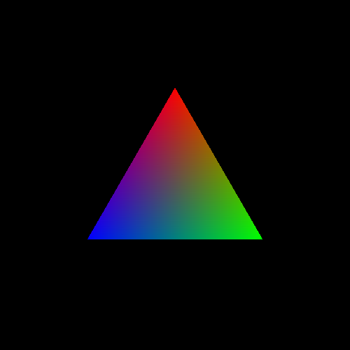
the best tool for controlling the color of triangles. A much more useful tool is to give
each vertex a color explicitly. The Vertex Colors
tutorial implements this; the main file for this tutorial is
VertexColors.cpp.
We want to affect the data being passed through the system. The sequence of events we want to happen is as follows.
For every position that we pass to a vertex shader, we want to pass a corresponding color value.
For every output position in the vertex shader, we also want to output a color value that is the same as the input color value the vertex shader received.
In the fragment shader, we want to receive an input color from the vertex shader and use that as the output color of that fragment.
You most likely have some serious questions about that sequence of events, notably about how steps 2 and 3 could possibly work. We'll get to that. We will follow the revised flow of data through the OpenGL pipeline.
In order to accomplish the first step, we need to change our vertex array data. That data now looks like this:
Example 2.2. New Vertex Array Data
const float vertexData[] = {
     0.0f,    0.5f, 0.0f, 1.0f,
     0.5f, -0.366f, 0.0f, 1.0f,
    -0.5f, -0.366f, 0.0f, 1.0f,
     1.0f,    0.0f, 0.0f, 1.0f,
     0.0f,    1.0f, 0.0f, 1.0f,
     0.0f,    0.0f, 1.0f, 1.0f,
};
First, we need to understand what arrays of data look like at the lowest level. A single byte is the smallest addressible data in C/C++. A byte represents 8 bits (a bit can be 0 or 1), and it is a number on the range [0, 255]. A value of type float requires 4 bytes worth of storage. Any float value is stored in 4 consecutive bytes of memory.
A sequence of 4 floats, in GLSL parlance a vec4, is exactly that: a
sequence of four floating-point values. Therefore, a vec4 takes
up 16 bytes, 4 floats times the size of a float.
The vertexData variable is one large array of floats. The way
we want to use it however is as two arrays. Each 4 floats is a single
vec4, and the first three vec4s represents the
positions. The next 3 are the colors for the corresponding vertices.
In memory, the vertexData array looks like this:

The top two show the layout of the basic data types, and each box is a byte. The bottom diagram shows the layout of the entire array, and each box is a float. The left half of the box represents the positions and the right half represents the colors.
The first 3 sets of values are the three positions of the triangle, and the next 3
sets of values are the three colors at these vertices. What we really have is two
arrays that just happen to be adjacent to one another in memory. One starts at the
memory address &vertexData[0], and the other starts at the
memory address &vertexData[12]
As with all vertex data, this is put into a buffer object. We have seen this code before:
Example 2.3. Buffer Object Initialization
void InitializeVertexBuffer()
{
    glGenBuffers(1, &vertexBufferObject);

    glBindBuffer(GL_ARRAY_BUFFER, vertexBufferObject);
    glBufferData(GL_ARRAY_BUFFER, sizeof(vertexData), vertexData, GL_STATIC_DRAW);
    glBindBuffer(GL_ARRAY_BUFFER, 0);
}
The code has not changed, because the sizes of the array is computed by the
compiler with the sizeof directive. Since we added a few elements
to the buffer, the computed size naturally grows bigger.
Also, you may notice that the positions are different from prior tutorials. The original triangle, and the one that was used in the Fragment Position code, was a right triangle (one of the angles of the triangle is 90 degrees) that was isosceles (two of its three sides are the same length). This new triangle is an equilateral triangle (all three sides are the same length) centered at the origin.
Recall from above that we are sending two pieces of data per-vertex: a position and a color. We have two arrays, one for each piece of data. They may happen to be adjacent to one another in memory, but this changes nothing; there are two arrays of data. We need to tell OpenGL how to get each of these pieces of data.
This is done as follows:
Example 2.4. Rendering the Scene
void display()
{
    glClearColor(0.0f, 0.0f, 0.0f, 0.0f);
    glClear(GL_COLOR_BUFFER_BIT);

    glUseProgram(theProgram);

    glBindBuffer(GL_ARRAY_BUFFER, vertexBufferObject);
    glEnableVertexAttribArray(0);
    glEnableVertexAttribArray(1);
    glVertexAttribPointer(0, 4, GL_FLOAT, GL_FALSE, 0, 0);
    glVertexAttribPointer(1, 4, GL_FLOAT, GL_FALSE, 0, (void*)48);

    glDrawArrays(GL_TRIANGLES, 0, 3);

    glDisableVertexAttribArray(0);
    glDisableVertexAttribArray(1);
    glUseProgram(0);

    glutSwapBuffers();
    glutPostRedisplay();
}
Since we have two pieces of data, we have two vertex attributes. For each
attribute, we must call glEnableVertexAttribArray to enable
that particular attribute. The first parameter is the attribute location set by the
layout(location) field for that attribute in the vertex
shader.
Then, we call glVertexAttribPointer for each of the attribute
arrays we want to use. The only difference in the two calls are which attribute
location to send the data to and the last parameter. The last parameter is the byte
offset into the buffer of where the data for this attribute starts. This offset, in
this case, is 4 (the size of a float) * 4 (the number of
floats in a vec4) * 3 (the number of
vec4's in the position data).
Note
If you're wondering why it is (void*)48 and not just
48, that is because of some legacy API cruft. The reason
why the function name is glVertexAttrib“Pointer” is because the
last parameter is technically a pointer to client memory. Or at least, it could
be in the past. So we must explicitly cast the integer value 48 to a pointer
type.
After this, we use glDrawArrays to render, then disable the
arrays with glDisableVertexAttribArray.
In the last tutorial, we skimmed over the details of what exactly
glDrawArrays does. Let us take a closer look
now.
The various attribute array functions set up arrays for OpenGL to read from when rendering. In our case here, we have two arrays. Each array has a buffer object and an offset into that buffer where the array begins, but the arrays do not have an explicit size. If we look at everything as C++ pseudo-code, what we have is this:
Example 2.5. Vertex Arrays
GLbyte *bufferObject = (void*){0.0f, 0.5f, 0.0f, 1.0f, 0.5f, -0.366f, ...};
float *positionAttribArray[4] = (float *[4])(&(bufferObject + 0));
float *colorAttribArray[4] = (float *[4])(&(bufferObject + 48));
Each element of the positionAttribArray contains 4
components, the size of our input to the vertex shader (vec4). This is the case
because the second parameter of glVertexAttribPointer is 4.
Each component is a floating-point number; similarly because the third parameter
is GL_FLOAT. The array takes its data from
bufferObject because this was the buffer object that was
bound at the time that glVertexAttribPointer was called.
And the offset from the beginning of the buffer object is 0 because that is the
last parameter of glVertexAttribPointer.
The same goes for colorAttribArray, except for the offset
value, which is 48 bytes.
Using the above pseudo-code representation of the vertex array data,
glDrawArrays would be implemented as follows:
Example 2.6. Draw Arrays Implementation
void glDrawArrays(GLenum type, GLint start, GLint count)
{
    for(GLint element = start; element < start + count; element++)
    {
        VertexShader(positionAttribArray[element], colorAttribArray[element]);
    }
}
This means that the vertex shader will be executed count
times, and it will be given data beginning with the start-th
element and continuing for count elements. So the first time
the vertex shader gets run, it takes the position attribute from
bufferObject[0 + (0 * 4 * sizeof(float))] and the color
attribute from bufferObject[48 + (0 * 4 * sizeof(float))].
The second time pulls the position from bufferObject[0 + (1 * 4 *
sizeof(float))] and color from bufferObject[48 + (1 * 4 *
sizeof(float))]. And so on.
The data flow from the buffer object to the vertex shaders looks like this now:

As before, every 3 vertices process is transformed into a triangle.
Our new vertex shader looks like this:
Example 2.7. Multi-input Vertex Shader
#version 330

layout (location = 0) in vec4 position;
layout (location = 1) in vec4 color;

smooth out vec4 theColor;

void main()
{
    gl_Position = position;
    theColor = color;
}
There are three new lines here. Let us take them one at a time.
The declaration of the global color defines a new input for the
vertex shader. So this shader, in addition to taking an input named
position also takes a second input named
color. As with the position input, this
tutorial assigns each attribute to an attribute index. position
is assigned the attribute index 0, while color is assigned
1.
That much only gets the data into the vertex shader. We want to pass this data out
of the vertex shader. To do this, we must define an output
variable. This is done using the out keyword. In
this case, the output variable is called theColor and is of type
vec4.
The smooth keyword is an interpolation
qualifier. We will see what this means in a bit later.
Of course, this simply defines the output variable. In main,
we actually write to it, assigning to it the value of color that
was given as a vertex attribute. This being shader code, we could have used some
other heuristic or arbitrary algorithm to compute the color. But for the purpose of
this tutorial, it is simply passing the value of an attribute passed to the vertex
shader.
Technically, the built-in variable gl_Position is defined as
out vec4 gl_Position. So it is an output variable as well. It
is a special output because this value is directly used by the system, rather than
used only by shaders. User-defined outputs, like theColor above,
have no intrinsic meaning to the system. They only have an effect in so far as other
shader stages use them, as we will see next.
The new fragment shader looks like this:
Example 2.8. Fragment Shader with Input
#version 330

smooth in vec4 theColor;

out vec4 outputColor;

void main()
{
    outputColor = theColor;
}
This fragment shader defines an input variable. It is no coincidence that this
input variable is named and typed the same as the output variable from the vertex
shader. We are trying to feed information from the vertex shader to the fragment
shader. To do this, OpenGL requires that the output from the previous stage have the
same name and type as the input to the next stage. It also must use the same
interpolation qualifier; if the vertex shader used smooth, the
fragment shader must do the same.
This is a good part of the reason why OpenGL requires vertex and fragment shaders to be linked together; if the names, types, or interpolation qualifiers do not match, then OpenGL will raise an error when the program is linked.
So the fragment shader receives the value output from the vertex shader. The shader simply takes this value and copies it to the output. Thus, the color of each fragment will simply be whatever the vertex shader passed along.
Now we come to the elephant in the room, so to speak. There is a basic communication problem.
See, our vertex shader is run only 3 times. This execution produces 3 output
positions (gl_Position) and 3 output colors
(theColor). The 3 positions are used to construct and
rasterize a triangle, producing a number of fragments.
The fragment shader is not run 3 times. It is run once for every fragment produced by the rasterizer for this triangle. The number of fragments produced by a triangle depends on the viewing resolution and how much area of the screen the triangle covers. An equilateral triangle the length of who's sides are 1 has an area of ~0.433. The total screen area (on the range [-1, 1] in X and Y) is 4, so our triangle covers approximately one-tenth of the screen. The window's natural resolution is 500x500 pixels. 500*500 is 250,000 pixels; one-tenth of this is 25,000. So our fragment shader gets executed about 25,000 times.
There's a slight disparity here. If the vertex shader is directly communicating with the fragment shader, and the vertex shader is outputting only 3 total color values, where do the other 24,997 values come from?
The answer is fragment interpolation.
By using the interpolation qualifier smooth when defining the
vertex output and fragment input, we are telling OpenGL to do something special with
this value. Instead of each fragment receiving one value from a single vertex, what
each fragment gets is a blend between the three output values
over the surface of the triangle. The closer the fragment is to one vertex, the more
that vertex's output contributes to the value that the fragment program
receives.
Because such interpolation is by far the most common mode for communicating
between the vertex shader and the fragment shader, if you do not provide an
interpolation keyword, smooth will be used by default. There are
two other alternatives: noperspective and
flat.
If you were to modify the tutorial and change smooth to
noperspective, you would see no change. That does not mean a
change did not happen; our example is just too simple for there to actually be a
change. The difference between smooth and
noperspective is somewhat subtle, and only matters once we
start using more concrete examples. We will discuss this difference later.
The flat interpolation actually turns interpolation off. It
essentially says that, rather than interpolating between three values, each fragment
of the triangle will simply get the first of the three vertex shader output
variables. The fragment shader gets a flat value across the surface of the triangle,
hence the term “flat.”
Each rasterized triangle has its own set of 3 outputs that are interpolated to compute the value for the fragments created by that triangle. So if you render 2 triangles, the interpolated values from one triangle do not directly affect the interpolated values from another triangle. Thus, each triangle can be taken independently from the rest.
It is possible, and highly desirable in many cases, to build multiple triangles from shared vertices and vertex data. But we will discuss this at a later time.